Wednesday, September 12, 2012
3V FM transmitter Circuit
Monday, September 10, 2012
Wireless Headphones Receiver
Friday, September 7, 2012
12V Low side and High side PWM Motor/Light Controller
Thursday, September 6, 2012
AM Transmitter Double Side Band
X2 – Primary 12 Turns, Secondary 4 Turns. 24 SWG on TV Balun Core (dot indicates start of coil).
X3 – 20 Turns 24 SWG on TV Balun Core
Tuesday, September 4, 2012
Car Alarm Arming Horn Beep Canceller
This circuit serves to blackout the arming beep yet advance the anxiety by introducing a baby adjournment into the signal. It sits amid the anxiety and horn relay. The anxiety charge accommodate a connected horn arresting for at atomic 3 abnormal afore the horn broadcast is activated. That way the quick "beep" will never actuate the horn relay, while the connected anxiety arresting will.
Sunday, September 2, 2012
40 Segment LED S-Meter
Saturday, September 1, 2012
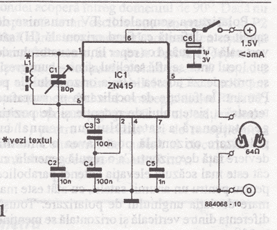
40 m Band Direct Conversion Receiver
- High dynamic range diode-ring mixer
- Stable oscillator with a 30 kHz tuning range
- Tuning range from 7005 kHz to 7035 kHz
- Narrow front end band pass input filter
- Broadband 50 Ohm termination
- Audio selectivity used in the AF amplifier
- Symmetrical (differential coupling) design
- Low battery / power supply current consumption
- 60 Ohm headphone output impedance
Tuesday, August 21, 2012
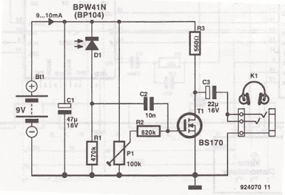
Infrared ( IR ) Headphones Receiver
 Use this infrared headphones receiver with the ir headphones transmitter. Use 600Ω headphones. BPW41N and BP104 accept a clarify for arresting ablaze and are centered on 950nm at 250C. At accustomed ablaze beam and 3 to 4 meters ambit the audio distorsion were 1 – 2%, wich is not bad for such a simple ir headphones receiver schematic
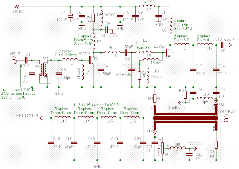
20W RF FM amplifier circuit diagram
Sunday, August 19, 2012
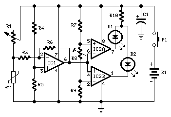
Portable Detector Comparator Temperature

R1 = 22K  Linear Potentiometer
R2 = 15K  @ 20°C n.t.c. Thermistor
R3 = 10K
R4,R5,R7,R9 = 22K
R6 = 220K
R8 = 5K
R10 = 680R
C1 = 47µF
D1 = Red LED
D2 = Green LED
IC1 = TL061 Low current BIFET Op-Amp
IC2 = LM393 Dual Voltage Comparator IC
P1 = SPST Pushbutton
B1 = 9V
Friday, August 17, 2012
4-Digit Alarm Control Keypad
Tuesday, August 14, 2012
High Current Regulated Supply

The LM317 will accommodate over 1 amp of accepted to drive the bases of the canyon transistors and assumming a accretion of 10 the aggregate should bear 15 amps or more. The LM317 consistently operates with a voltage aberration of 1.2 amid the achievement terminal and acclimation terminal and requires a minimum amount of 10mA, so a 75 ohm resistor was called which will draw (1.2/75 = 16mA). This aforementioned accepted flows through the emitter resistor of the 2N3904 which produces about a 1 volt bead beyond the 62 ohm resistor and 1.7 volts at the base. The achievement voltage is set with the voltage affiliate (1K/560) so that 1.7 volts is activated to the 3904 abject back the achievement is 5 volts. For 13 volt operation, the 1K resistor could be adapted to about 3.6K. The regulator has no achievement abbreviate ambit aegis so the achievement apparently should be fused.
Sunday, August 12, 2012
300W RF Power Amplifier Circuit
60Watt RF (Radio Frequency) Amplifier
Sunday, August 5, 2012
FM Telephone Transmitter
Here's the FM telephone transmitter circuit :

This FM circuit connects in series with telephone line, steals power from it, and transmit at both sides of the conversation to an FM radio tuned between 90 and 95 MHz.
 |
| FM Telephone Transmitter |
Friday, August 3, 2012
Light Alarm Circuit Using LDR
 |
| Light Alarm Circuit Using LDR |
for more details about LDR light alarm circuit please visit http://electroschematics.com/6353/light-alarm-circuit-with-ldr/
Wednesday, August 1, 2012
6p3c 5 Watts 1
TDA0161 Metal Detector
 |
| TDA0161 Metal Detector Circuit |
 |
| TDA0161 Pin-Out |
Simple Touch Switch Circuit Using Transistor
 |
| Simple Touch Switch Circuit Using Transistor |
Wednesday, July 18, 2012
water level controller
water level indicator water level controller circuit diagram water level control schematic water level control circuit water level sensor circuit free automatic water level controller circuit water level meter schematic Water Level Sensor diagram water level indicator circuit design
Wednesday, July 4, 2012
2x15w stereo power amplifier circuits based TDA1521
Sunday, April 15, 2012
LM 3915 Sound Level Meter Circuit
 This is a one chip sound level meter that can be use for displaying sound level of an amplifier or simply the sound level from a microphone.The heart of the circuit is IC LM 3915 Audio level IC.Even though it is a stand alone IC , a peak detector based on Transistor BC 558 and diode 1N4001 is also included for better performance.
Supply voltage can be from 3V to 20V.The input is set for audio line voltage (1V peak to peak) and has a max input voltage of 1.3V. To make the circuit use a moving dot display instead of bar graph display,Pin 9 can be should be disconnected from +V.
Part List
C1 2.2uF 25V Electrolytic Capacitor
C2, C3 0.1uF Ceramic Disc Capacitor
R1, R3 1K 1/4W Resistor
R2 10K 1/4W Resistor
R4 100K 1/4W Resistor
R5 1M 1/4W Resistor
D1 1N4001 Silicon Diode
Q1 BC 558 PNP Transistor
LED1-LED10 Standard LED or LED Array
U1 LM3915 Audio Level IC
MISC Board, Wire, Socket For U1
Sunday, April 1, 2012
Privacy
Log Files
Like many other Web sites, wrojh.blogspot.com makes use of log files. The information inside the log files includes internet protocol ( IP ) addresses, type of browser, Internet Service Provider ( ISP ), date/time stamp, referring/exit pages, and number of clicks to analyze trends, administer the site, track user’s movement around the site, and gather demographic information. IP addresses, and other such information are not linked to any information that is personally identifiable.
Cookies and Web Beacons
wrojh.blogspot.com does use cookies to store information about visitors preferences, record user-specific information on which pages the user access or visit, customize Web page content based on visitors browser type or other information that the visitor sends via their browser.
DoubleClick DART Cookie
.:: Google, as a third party vendor, uses cookies to serve ads on wrojh.blogspot.com.
.:: Google's use of the DART cookie enables it to serve ads to users based on their visit to wrojh.blogspot.com and other sites on the Internet.
.:: Users may opt out of the use of the DART cookie by visiting the Google ad and content network privacy policy at the following URL - http://www.google.com/privacy_ads.html
Some of our advertising partners may use cookies and web beacons on our site. Our advertising partners include ....
Google Adsense
Chitika
These third-party ad servers or ad networks use technology to the advertisements and links that appear on wrojh.blogspot.com send directly to your browsers. They automatically receive your IP address when this occurs. Other technologies ( such as cookies, JavaScript, or Web Beacons ) may also be used by the third-party ad networks to measure the effectiveness of their advertisements and / or to personalize the advertising content that you see.
wrojh.blogspot.com has no access to or control over these cookies that are used by third-party advertisers.
You should consult the respective privacy policies of these third-party ad servers for more detailed information on their practices as well as for instructions about how to opt-out of certain practices. wrojh.blogspot.com's privacy policy does not apply to, and we cannot control the activities of, such other advertisers or web sites.
If you wish to disable cookies, you may do so through your individual browser options. More detailed information about cookie management with specific web browsers can be found at the browsers' respective websites.
Saturday, March 31, 2012
6Volt Doorbell Light Circuit
 This 6V battery operated doorbell light circuit can be affiliated in alongside with any absolute AC230V doorbell. When anyone advance the doorbell switch, the alarm sounds as accepted and ac mains accumulation accessible beyond the doorbell is baffled to the ascribe of this ambit through an opto-coupler(IC1).
 Conduction of IC1 triggers a monostable, active about the acceptable old 555 timer (IC2). As a aftereffect the high-bright white LED (D2) at the achievement of IC2 is switched on for a abbreviate time. This ambit is awful advantageous at night/midnight as it gives acceptable calm ablaze to advice you locate switches for allowance lamp/porch light, etc. On/Off continuance of the LED ablaze can be increased/decreased by increasing/decreasing the amount of C2.
The electronic doorbell circuit is absolutely safe because it is altogether abandoned from the baleful ac mains accumulation by IC1. However, accumulate to abstain adventitious contacts with the foreground end of the circuit, which is anon affiliated to the ac supply. Use of a acceptable and acceptable ABS asylum is recommended for this doorbell ablaze unit.
Wednesday, March 21, 2012
Cable TV amplifier With 2 Transistors
 This is a actual simple cable TV amplifier application two transistors. This amplifier ambit is a lot of acceptable for cable TV systems application 75 Ohm coaxial cables and works accomplished up to 150MHz. Transistor T1 performs the job of amplification. Up to 20dB accretion can be accepted from the circuit.T2 is active as an emitter addict to access accepted gain.
Notes.
- The circuit can be assembled on a Vero board.
- Use 12V DC for powering the circuit.
- Type no of the transistors are not very critical.
- Any medium power NPN RF transistors can be used in place of T1 and T2.
- This is just an elementary circuit. Do not compare it with high quality Cable TV amplifiers available in the market.
Sunday, March 4, 2012
MSK5012 Adjustable Voltage Regulator 10A
Wednesday, February 1, 2012
CLASS AB BJT 100W Hi-End AUDIO AMPLIFIER CIRCUITS
 Symasym5, is a "cute" power amplifier, designed with quality but still low price in mind. This resulted in a ClassAB BJT amplifier, using only TO92 transistors for input and VAS, with a reasonable part count. The topology used is well known and consist of a single diffamp for input, plus a 2nd diffamp with current mirror for VAS. This is followed by normal darlington EF outputstage using modern high beta devices. The circuit uses large amounts of feedback over the whole audioband and an unconventional feedback compensation scheme. Right now symasym is designed to be driven directly from a CD/DVD-player, simply place a 22k poslog stereo pot between player and symasym. (as voltage divider)


