Thursday, July 28, 2011
IRF44 Mosfet based on 100 Watt Inverter Circuit
This inverter circuit can offer a really stable 230V Output Voltage. Frequency of operation is decided by a VR1 and is generally set to 60 Hz. varied “off the shelf” transformers can be used. Or Custom wind your own for best results. additional MosFets can be paralleled for higher power. it's recommended to own a “Fuse” within the Power Line and to perpetually have a “Load connected”, while power is being applied. The Fuse ought to be10 Amps per one hundred watts of output. the ability leads must be serious enough wire to handle this High Current Draw.

Absolute Maximum Ratings of IRF44 Mosfet
- Continuous Drain Current (25°C, 10V) = 49 A
- Continuous Drain Current ( 100°C, 10V) = 35 A
- Pulsed Drain Current = 160 A
- Power Dissipation = 94 W
- Gate-to-Source Voltage = ± 20 V
- Avalanche Current = 25 A
- Operating Junction = -55 to + 175
Monday, July 25, 2011
LM3875-High Audio Amplifier 56W

The LM3875 is an audio amplifier for high power output capable of delivering 56W of continuous average power to a load 8. The performance of the LM3875, utilizing its maximum instantaneous auto temperature (° Ke) (Spike ™) protection circuitry, places it in a class above discrete and hybrid amplifiers by providing a yes, dynamically protected area of safe operation (SOA). SPIKE protection means that these parts are fully protected against output overvoltage, voltage surges caused by shorts to the supplies, the peak temperature thermal runaway, and instantaneous.
This amplifier circuit is based on the non-inverted GainClone standard configuration. I did some calucaltions the feedback resistor and other components in order to check the gain, etc. For more background on the calculations relevant to GainClones in the background section.
 Parameters IC LM3875
Output Current 6000 mA.
Offset Voltage max, 25C 10 mV.
Gain Bandwidth 8 MHz.
Supply Min 20 Volt.
Supply Max 84 Volt.
Supply Current Per Channel 30 mA.
PowerWise Rating 2 3750 uA/MHz.
Slew Rate 11 Volts/usec.
Input OutputType Not Rail to Rail.
Max Input Bias Current 1000 nA.
Special Features AvCl>10.
Function Op Amp.
Channels 1 Channels.
Temperature Min 0 deg C.
Temperature Max 70 deg C.
Friday, July 22, 2011
12 watt FM Transmitter circuit
The advantages of FM modulation is free from the influence of the disturbance of air, bandwidth (broadband) is larger, and the high fidelitas. Compared to the AM system.
FM transmitter is a modification of the FM transmitter on the market (s Saturn type 038). several series of modifications and additions can produce energy Boster number to about 12 watts.
of the series after this work is quite good, the signal generated is stable and strong enough
time in no hurry to do it directly, but usually do each part in sequence so that the error may be earlier
the first part of the work is in the oscillator, after the raft can try to turn radio waves in free mode and set the radio volume so clearly audible hiss. turn the core Koker whistle on the radio is, if you get a signal in a robust and stable set of oscillator has been working with both.
the next section can start at the raft, after the end of the second set trimer (C8 and C11) in the buffer, in turn can feed even the largest steel cables and the older children. If the series works well, there are approximately 0.25 watts
for more resources that can be added over the wider range Boster 12 watts, so the distance will be increased to up to seven times.
Wednesday, July 20, 2011
Audio Amplifier Using IC LM4780
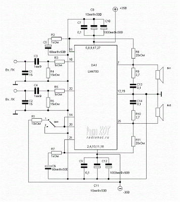
Explore power amplifier integrated circuit from National Semiconductor LM4780. What's so special? Well, first of all - a very low harmonic distortion. In general, manufacturers indicate the maximum power of his ingenious craft regularly with the harmonic content of 10%. At the same chip, CT in the specified maximum power is only 0.5%! Therefore, it is the most honest of all mikruha've found.
The chip implements two identical amplifier channels and features are given for the stereo amplifier. Circuit can also operate in mono - the inclusion of the bridge. In this case, the power output at CT = 0.5% of 120 watts. Other features remain virtually unchanged.
LM4780 IC Fiture
- Features SPiKe Protection
- Low external component count
- Quiet fade-in/out mute mode
- Wide supply range: 20V - 84V
- Signal-to-Noise Ratio ≥ 97dB (ref. to PO = 1W)


Sunday, July 17, 2011
LM2678-5.0 on 5Volt Switching Regulator


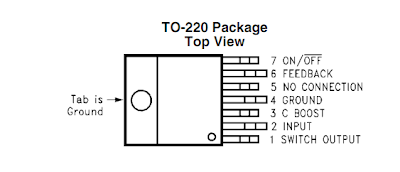
This is the circuit diagram of a 5V power regulator based on LM2678 IC. The LM2678 series of regulators are monolithic integrated circuits that provide all the necessary functions required for a switching regulator money and can handle loads up to 5A. The IC has more than 90% efficiency and has to load and line regulation. The LM2678 is available in three fixed output voltages (3.3 V, 5V, 12V) and an adjustable output version. The IC is also filled with a bunch of l features such as thermal shutdown, current limiting and power on / off.
Note:
- The circuit given here is based on the version LM2678-5.0 which gives an output of 5V.
- The power supply for the circuit can be anything between 8 to 40V DC.
- The feedback wiring must be placed as away as possible from the inductor L1.
- Do not use loads that consume more than 5A.
- A heat sink is seriously recommended for the IC.
Friday, July 15, 2011
Audio Surround Decoder circuit diagram

This circuit has been created to design a decoder circuit that will function in a module that produces surround sound audio.
The operation of the circuit starts up and transport the stereo surround sound signal quality information on the master volume circuit. This will drive the left channel connected to LCH Model TL072 IC1A IC1B and attached to the right channel Rch. The outputs of these operational amplifiers serve as the input buffer for the next stages of the circuit. IC2C is responsible for the sum of the signals from left and right to power the center speaker output, while IC2D is responsible for increasing the phase difference between left and right, which is encoded in the two channels and be fed to the rear speakers. It is necessary to ensure that the negative terminals from the rear speakers is not grounded, since it will only work in parallel with the main speakers.
The output of the power unit regulated IC2D takes audio to rear speakers. This would lead to the creation of sense of separation, according to the size of the room. This will incorporate signal amplifier IC5 MN3004 sound delay that has 512 steps. From IC4 MN3101 is a timing signal, which provides synchronization of IC5 as it functions as an oscillator in the circuit. C17 variable capacitor regulates the delay in the circuit. The presence of filters in the circuit is in order to avoid the noise that occurs during the process.
These filters can be adjusted to cut the frequencies above 8 kHz and below 100 Hz, to be able to drive the rear speaker. The rear speaker is small and that their entry is encoded with a bandwidth of 100 Hz to 8 KHz. The filters are built around the IC6A / B is also an output buffer. A potentiometer is placed on each output to aid in the adjustment and regulation of speakers and amplifiers. The energy supplied in the circuit is 15 V and each output can drive a single power amplifier.
List Compoment
R1-2-7-8-12-13-18-19-20 : 47Kohm
R3-4-5-6-21-22-34-35    : 10Kohm
R9-10-11-14-15-16-17    : 15Kohm
R23-24-25-33-36         : 100ohm
R26-27-28-31-32         : 100Kohm
R29-30                  : 5.6Kohm
C1-8                    : 47uF/25V
C2-7-9-14-23            : 47nF
C3-6                    : 1uF/100V
C4-5-10                 : 33pF
C11-12-15               : 10uF/25V
C13                     : 82nF
C16                     : 18pF
C17                     : 100pF mini adjustable capacitor
C18                     : 2.2nF
C19                     : 4.7uF/25V
C20                     : 100nF
C21                     : 10nF
C22                     : 180pF
C24                     : 150nF
RV1-RV2                 : 2 X 10Kohm  Log. pot.
RV3-4                   : 10K Log pot.
D1                      : 1N4148
IC1-6                   : TL072
IC2-3                   : TL074
IC4                     : MN3101
IC5                     : MN3004
Wednesday, July 13, 2011
12 Volt car Battery Monitor Circuit
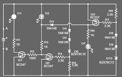
This circuit can be used to monitor the voltage level of a car battery. When the battery voltage is 11.5V or less the transistor Q1 is on and D1 glowing.When LED battery voltage is between 11.5 to 13.5 V, the transistor Q2 is on and the glowing LED D2 .
When the battery voltage is above 13.5 V, the transistor Q3 is on and the LED D3 will be bright. The 12 volt control can be connected between terminals A and B and for the convenience of using LEDs of different colors.
List component of Monitor status battery 12 volt
-R1,R3,R6: 1k 1/4W Resistance
-R2: 100K 1/4W Resistance
-R4,R5,R7,R8: 3.3K 1/4W Resistance
-D1: LED red color
-D2: LED yellow color
-d7: LED green COLOR
-D2,D4,D5,D8,D9: 1N4148 diode 1 ampere
-D6: BZX79C10 diode Zener 10 volt
-D10: BZX79C12 diode Zener 12 volt
-Q1,Q2: BC547 NPN transistor
-Q3: BC557 PNP transistor
Sunday, July 10, 2011
12VDC – 220VAC Inverter Using Cmos CD4047

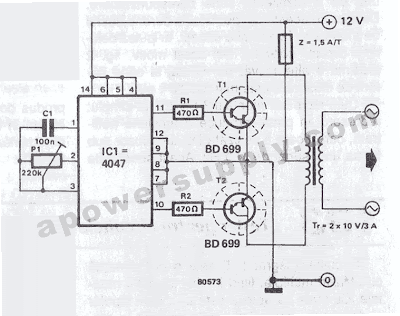
This circuit inverter converts 12V DC battery to AC 22oV as the replacement of home energy. The inverter can be used for small electronic devices such as lamps, radio, phone charger, disc player, etc.

The inverter circuit is a central component, the CMOS 4047, and converts a DC voltage of 12 V to 220 V AC voltage. 4047 is used as an astable multivibrator. The pin 10 and 11 we find a symmetrical rectangular signal is amplified by Darlington transistors T1 and T2 trailer, and finally reaches the secondary coil of a transformer of the network (2 x 10V/100VA). Primary coil voltage is 220 AC voltage terminals. For best performance, use a toroidal core transformer with low losses. P1 to the output frequency can be regulated within certain limits (50 ... 400 Hz).
Thursday, July 7, 2011
Thermometer Based on Mikrokontroler AT89S52


This is a circuit of a microcontroller AT89S52 thermometer and LTC1298 12-bit ADC, programs written in C language program with digital filtering and interface the LED display. Reading provides a sensitivity 0.1C.
The hardware block and circuit diagram is shown in the figure below. The thermistor sensor is epoxy. The signal conditioning circuit is a simple voltage divider. The ADC is 12-bit SPI interface LTC1298 analog to digital. Atmel's Microcontroller 89S52. The 0.5 inch display has four digits of 7 segments. The driver of the segment offers 32-bit CMOS output.
The 12-bit ADC (LTC1298 or MC3202) are two channels, CH0 and CH1. The signal from ADC input channel 0 thermistor voltage divider is simple. Channel 1 is available for other sensors. The example shown in the diagram is the HIH-3160 Honeywell Relative Humidity Sensor. The ADC chip interconnects with MCU 89S52 with P1.1, P1.2 and P1.3. The LED display has 4 digits. The CMOS shift register 4094 directly drives the LED
Tuesday, July 5, 2011
Fm transmitter 88-108Mhz - IC MAX2606
This is a FM transmitter circuit with semiconductor Maxim MAX2606 IC. In the circuit of rated frequency is 100 MHz for L1 inductor (390nH). Signals from the left and right channels of audio from its origin are added by R3 and R4, and attenuated by R2 POT. R2 can be used as a volume control. POT R1 can be used to select a transmission channel between 88MHz and 80 cm cable 108Mhz.Use long as the antenna.
Note:
* Use a battery for powering the circuit.It will reduce noise.
* An FM antenna from a old radio is a better option than the wire antenna.
IC MAX2606 Description
The MAX2605, MAX2609 are compact, high performance intermediate frequency (IF) voltage-controlled oscillator (VCO) designed specifically for demanding portable wireless communication systems. They combine monolithic construction with low noise, low operating power consumption of a small 6-pin SOT23 package.
Low-noise VCO, a feature on-chip varactor and feedback capacitors that eliminate the need for external adjustment elements, so the ideal MAX2605, MAX2609 for portable systems. Only an external coil is needed to establish the frequency of oscillation. In addition, a buffer integrated differential output is provided for driving a mixer or prescaler. The output buffer is capable of providing up-8dBm (differential) with a simple power game. It also provides isolation from load impedance variations.
The MAX2605, MAX2609 operate from a single 2.7 V to 5.5 V supply and provides low power consumption. IF these oscillators can cover the frequency range of 45MHz to 650MHz.
 IC MAX2606 Absolute Maximum Rating
Note:
* Use a battery for powering the circuit.It will reduce noise.
* An FM antenna from a old radio is a better option than the wire antenna.
IC MAX2606 Description
The MAX2605, MAX2609 are compact, high performance intermediate frequency (IF) voltage-controlled oscillator (VCO) designed specifically for demanding portable wireless communication systems. They combine monolithic construction with low noise, low operating power consumption of a small 6-pin SOT23 package.
Low-noise VCO, a feature on-chip varactor and feedback capacitors that eliminate the need for external adjustment elements, so the ideal MAX2605, MAX2609 for portable systems. Only an external coil is needed to establish the frequency of oscillation. In addition, a buffer integrated differential output is provided for driving a mixer or prescaler. The output buffer is capable of providing up-8dBm (differential) with a simple power game. It also provides isolation from load impedance variations.
The MAX2605, MAX2609 operate from a single 2.7 V to 5.5 V supply and provides low power consumption. IF these oscillators can cover the frequency range of 45MHz to 650MHz.
 IC MAX2606 Absolute Maximum Rating
- VCC to GND..............................................................-0.3V to +6V
- IND to GND ................................................-0.6V to (VCC + 0.3V)
- TUNE to GND .............................................-0.3V to (VCC + 0.3V)
- OUT+, OUT- to GND ..................................-0.3V to (VCC + 0.6V)
- Continuous Power Dissipation (TA = +85°C)
- 6-Pin SOT23 (derate 8.7mW/°C above +70°C)...........696mW
- Operating Temperature Range ...........................-40°C to +85°C
- Junction Temperature......................................................+150°C
- Storage Temperature Range .............................-65°C to +150°C
- Lead Temperature (soldering, 10s) .................................+300°C
Sunday, July 3, 2011
1000 Watt Power Amplifier Blazer

This is an audio amplifier circuit provides power to 1000 watts Blazer. This interesting routes under a lot of good and lively treble. Importantly, you should choose the power source, which has been quite high voltage class GND-70V 70Vdc 10A is the current low level
The transistors are 2SC3858 (NPN) and 2SA1494 (PNP) and the bandwidth characteristic of high, excellent area of safe operation, high linearity and high gain. 2SC5200 driver transistors (NPN) and 2SA1943 (PNP). All devices are rated at 230 V, with the power transistors has a dissipation of 150 W and the drivers are 50W.
This circuit describes a process amplifier, power supply and the tests that are inherently dangerous. Nothing described in this article should not even be considered unless a wealth of experience, we know exactly what you are doing and are willing to assume full responsibility for 100% of what you do. There are design issues that may require analysis, fault detection and / or modification.
Saturday, July 2, 2011
Electronic Mosquito Repellent Using IC 555
This circuit can help you by keeping the mosquito and similar Insects and other creatures away from you using a high frequency sound produced by this circuit.
The main principle in the which this electronic mosquito repellent works Is that mosquito and Insects are highly sensitive to some frequency of sound and They Do not like the sound. And Insects and mosquito Will leave or get away from you due to the annoying sound. But the sound it produces is of a high frequency of the which can not be Heard by Humans so you will not be affected by the sound.
 |
| Electronic Mosquito Repellent Circuit Using IC 555 |
In the circuit timer IC 555 is used as it generates an oscillator frequency of about 62 KHz, the working frequency of the circuit can be set by rotating the preset resistor R2, and the speaker converts the electronic frequency to sound frequency. Try to keep the frequency of the sound as high as possible. And Make sure you do not Hear the sound of this circuit by keeping it above 20 KHZ, the annoying sound Will be Heard by Insects but not by you Because Humans do not normally Hear the sound of higher frequency than 20 KHz.
for better results use a speaker of good quality in the circuit, using good quality speaker Will Ensure That Will the project work.
Friday, July 1, 2011
40khz (IR) Infrared Tester
 Use this circuit to test if the light source coming from your 40khz IR emitter is actually giving out the best frequency. The schematic says to apply a GP1U5X ir module, however probably any 40khz detector module will work.
Part list
R1 270 ohm resistor
L1 Visible LED
S1 On/Off Switch
IR Module Sharp GP1U5X IR Detect Module (or compatible)
L1 Visible LED
S1 On/Off Switch
IR Module Sharp GP1U5X IR Detect Module (or compatible)
BC548C Transistor Water Level Buzzer
This is the circuit of a simple buzzer corrosion free water level indicator for home and industries. This circuit is very simple because it uses only two transistors and some passip Components are easily found circulating in the electronics stores.
When the water reaches the sensor, BC548C Transistor base is connected to the positive terminal. In consequence the transistor is opening and the buzzer it makes a buzz. Function: In the water level indicator, buzzer will be activated in order to make a noise when a certain level of water is being reached.
Subscribe to:
Posts (Atom)


