Tuesday, June 4, 2013
Fuse Box Diagram Mercedes Benz R170


Fuse Panel Layout Diagram Parts: garage door opening signal, control
unit, child seat recognition system, indicator, exterior mirror
adjustment, roof light, horn, anti theft alarm, trunk light, ignition
coil, washer liquid heater, washer nozzle heater, sound booster, power
window, seat adjustment, hydraulic unit, control locking, cigar lighter,
glove compartment light, seat heater, instrument cluster, circulating
air
Tuesday, May 14, 2013
Pairs Simple Schematic Diagram Wiring
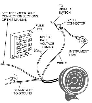
Installing A Tachometer In Your Ford Ranger.
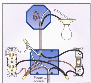
Light With Outlet 2 Way Switch Wiring Diagram.

In Pairs Above Is A Simple Schematic Diagram Of How The Wiring For.

Power At Light 4 Way Switch Wiring Diagram.
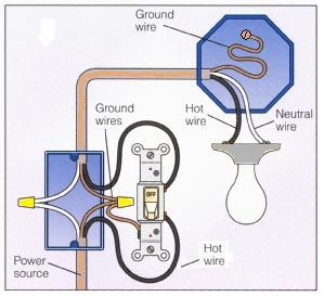
Basic 2 Way Switch Wiring Diagram.

Post It But I Ll Try To Diagram It Here.

Dodge Dakota Radio Wiring Diagram 1998 Dodge Ram 1500 Wiring Diagram.

Wiring Diagram For Manual Service Motorcycle Diagrams Collection.

Diagram Electrical Circuit Diagram Related Posts Wiring And Connectors.

Here Is A Typical Schematic Of Bentley Parrot 3200 Ls Wiring Diagram.
Sunday, May 5, 2013
Three Flashing LED Doorbells For The Hearing Impaired
When
the push switch is operated - the buzzer will sound and the LEDs will
begin to flash. For the hearing members of the household - the buzzer
acts as a regular doorbell. It also re-assures the visitor that the
doorbell is working.
When the push switch is released the buzzer will stop - but the LEDs will continue to flash. The length of time they will go on flashing is set by the values of R2 & C1. With the values shown in the diagram - the LEDs will flash for a further 30 seconds or so. If you make R2 a variable resistor, you can adjust the time period. If you want longer than 30 seconds - increase the value of C1 or R2.
When the push switch is released the buzzer will stop - but the LEDs will continue to flash. The length of time they will go on flashing is set by the values of R2 & C1. With the values shown in the diagram - the LEDs will flash for a further 30 seconds or so. If you make R2 a variable resistor, you can adjust the time period. If you want longer than 30 seconds - increase the value of C1 or R2.


The
main difference between this circuit and the last one - is the
addition of the two transistor switches. The switches will each flash up
to 15 groups of 3 LEDs. And - because they are getting power directly
from the battery - the LEDs will glow at their full brilliance.

Tuesday, April 30, 2013
3000 watt power inverter 12V DC to 230V AC
 |
| Circuit Diagram of 3000 watt power inverter 12V DC to 230V AC |
 |
| Fig. 2: Sine-wave voltage and conventional square wave voltage with both 230 Volt rms |
 |
| Fig. 3: Square wave voltage with duty cycle 25% for 230 Volt rms ("modified sine") |
PCB Layout:3000 watt power inverter 12V DC to 230V AC

Component Placement: 3000 watt power inverter 12V DC to 230V AC

 |
| fig.: output voltage with no load or inductive load. |
 |
| fig.: resistor 0,001 Ohm made of high-grade steel sheet metal |
Control electronics | 3000 watt power inverter 12V DC to 230V AC

 |
| fig.: control electronics on strip hole plate (previous version) and PCB of the "professional edition" |
Assembly of the mosfet-transistors on the heat sink | 3000 watt power inverter 12V DC to 230V AC

 |
| fig.: heat sink, mosfet transistors, connections. |
Final assembly | 3000 watt power inverter 12V DC to 230V AC

 |
| fig.: 1500 VA inverter with 2 parallel transformers and 1000 VA inverter |
Source:http://www.qsl.net
Tuesday, April 23, 2013
Animal Friendiy Mousetrap
This mousetrap is built around a PlC12F683 and uses an infrared transmissive optical sensor that is modulated at a frequency of 38 kHz, so that it isnt affected by the ambient light. The modulation is carried out by the PlC, which generates a 38 kHz signal at port GP2, which is connected to the lR LED. The lR receiver is a type that is usually found for use with remote controls. lt reacts only to 38 kHz signals. lt reports the presence of an lR signal to the PIC via port GP1.
When the lR lightbeam is broken the PIC turns of the relay via port GP4 and FET T1 , which: causes the door of the mousetrap to close. The transmissive optical sensor is housed inside a small wooden box. A small amount of food is placed inside this box.
Circuit diagram :
Animal Friendiy Mousetrap Circuit Diagram
When a mouse walks through the light beam on its way to the food it causes the door to shut behind it and an LED starts flashing. The door is normally kept open by the coil of a relay that has been taken apart. When the coil is no longer powered the tin door is pushed shut by means of a spring. A piece of glass or transparent plastic should be put on top of the box, so that the mouse doesnt have to enter a dark space. When a mouse has been caught it can be let free again somewhere outside, some distance away from the house.
The reset button has to be pressed to ready the trap for its next victim. The author has managed to catch a few dozen mice with this device. The program is written in PICBASIC Pro and can be freely downloaded from the Elektor website, it is found in archive file # 100308-11.zip.
Subscribe to:
Posts (Atom)