Tuesday, June 4, 2013
Fuse Box Diagram Mercedes Benz R170


Fuse Panel Layout Diagram Parts: garage door opening signal, control
unit, child seat recognition system, indicator, exterior mirror
adjustment, roof light, horn, anti theft alarm, trunk light, ignition
coil, washer liquid heater, washer nozzle heater, sound booster, power
window, seat adjustment, hydraulic unit, control locking, cigar lighter,
glove compartment light, seat heater, instrument cluster, circulating
air
Tuesday, May 14, 2013
Pairs Simple Schematic Diagram Wiring
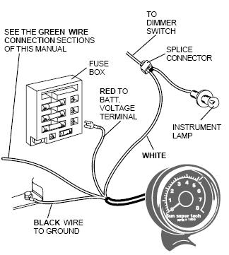
Installing A Tachometer In Your Ford Ranger.
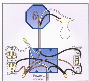
Light With Outlet 2 Way Switch Wiring Diagram.

In Pairs Above Is A Simple Schematic Diagram Of How The Wiring For.

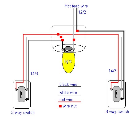
Power At Light 4 Way Switch Wiring Diagram.
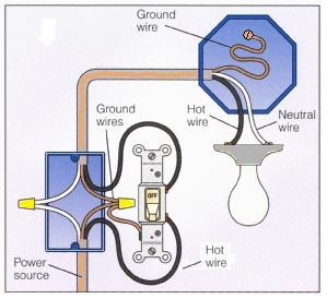
Basic 2 Way Switch Wiring Diagram.

Post It But I Ll Try To Diagram It Here.

Dodge Dakota Radio Wiring Diagram 1998 Dodge Ram 1500 Wiring Diagram.

Wiring Diagram For Manual Service Motorcycle Diagrams Collection.

Diagram Electrical Circuit Diagram Related Posts Wiring And Connectors.

Here Is A Typical Schematic Of Bentley Parrot 3200 Ls Wiring Diagram.
Sunday, May 5, 2013
Three Flashing LED Doorbells For The Hearing Impaired
When
the push switch is operated - the buzzer will sound and the LEDs will
begin to flash. For the hearing members of the household - the buzzer
acts as a regular doorbell. It also re-assures the visitor that the
doorbell is working.
When the push switch is released the buzzer will stop - but the LEDs will continue to flash. The length of time they will go on flashing is set by the values of R2 & C1. With the values shown in the diagram - the LEDs will flash for a further 30 seconds or so. If you make R2 a variable resistor, you can adjust the time period. If you want longer than 30 seconds - increase the value of C1 or R2.
When the push switch is released the buzzer will stop - but the LEDs will continue to flash. The length of time they will go on flashing is set by the values of R2 & C1. With the values shown in the diagram - the LEDs will flash for a further 30 seconds or so. If you make R2 a variable resistor, you can adjust the time period. If you want longer than 30 seconds - increase the value of C1 or R2.


The
main difference between this circuit and the last one - is the
addition of the two transistor switches. The switches will each flash up
to 15 groups of 3 LEDs. And - because they are getting power directly
from the battery - the LEDs will glow at their full brilliance.

Tuesday, April 30, 2013
3000 watt power inverter 12V DC to 230V AC
 |
| Circuit Diagram of 3000 watt power inverter 12V DC to 230V AC |
 |
| Fig. 2: Sine-wave voltage and conventional square wave voltage with both 230 Volt rms |
 |
| Fig. 3: Square wave voltage with duty cycle 25% for 230 Volt rms ("modified sine") |
PCB Layout:3000 watt power inverter 12V DC to 230V AC

Component Placement: 3000 watt power inverter 12V DC to 230V AC

 |
| fig.: output voltage with no load or inductive load. |
 |
| fig.: resistor 0,001 Ohm made of high-grade steel sheet metal |
Control electronics | 3000 watt power inverter 12V DC to 230V AC

 |
| fig.: control electronics on strip hole plate (previous version) and PCB of the "professional edition" |
Assembly of the mosfet-transistors on the heat sink | 3000 watt power inverter 12V DC to 230V AC

 |
| fig.: heat sink, mosfet transistors, connections. |
Final assembly | 3000 watt power inverter 12V DC to 230V AC

 |
| fig.: 1500 VA inverter with 2 parallel transformers and 1000 VA inverter |
Source:http://www.qsl.net
Tuesday, April 23, 2013
Animal Friendiy Mousetrap
This mousetrap is built around a PlC12F683 and uses an infrared transmissive optical sensor that is modulated at a frequency of 38 kHz, so that it isnt affected by the ambient light. The modulation is carried out by the PlC, which generates a 38 kHz signal at port GP2, which is connected to the lR LED. The lR receiver is a type that is usually found for use with remote controls. lt reacts only to 38 kHz signals. lt reports the presence of an lR signal to the PIC via port GP1.
When the lR lightbeam is broken the PIC turns of the relay via port GP4 and FET T1 , which: causes the door of the mousetrap to close. The transmissive optical sensor is housed inside a small wooden box. A small amount of food is placed inside this box.
Circuit diagram :
Animal Friendiy Mousetrap Circuit Diagram
When a mouse walks through the light beam on its way to the food it causes the door to shut behind it and an LED starts flashing. The door is normally kept open by the coil of a relay that has been taken apart. When the coil is no longer powered the tin door is pushed shut by means of a spring. A piece of glass or transparent plastic should be put on top of the box, so that the mouse doesnt have to enter a dark space. When a mouse has been caught it can be let free again somewhere outside, some distance away from the house.
The reset button has to be pressed to ready the trap for its next victim. The author has managed to catch a few dozen mice with this device. The program is written in PICBASIC Pro and can be freely downloaded from the Elektor website, it is found in archive file # 100308-11.zip.
Voice Activated Home Automation
Voice recognition is no
longer in infancy, especially since Siri just launched on the new
iPhone 4S (although similar technology is available on Android too.
This project shows you how to use it to automate your home without
spending big bucks.

The
core of this project is a VRBot speech recognition module. Next, the
project creator used some low-cost wireless light switches (you could
also use relays). The VRBot speech recognition module recognizes 32
custom voice commands. Once a command is recognized, a wireless
switch is activated via a radio receiver. The setup is simple after
you spend some time understanding the wireless communication protocol
between the different modules.
Automobile White crystal rectifier lightweight
Without any devoted buck converter/white crystal rectifier forcer IC, youll protectedly force several regular Hi-efficient white crystal rectifier modules victimization the battery power available in the market in automotives. Here could also be a protected and straightforward white crystal rectifier pressurer designed for 12V automobiles.
Auto White LED Circuit Schematic

In the Automobile White crystal rectifier wiring, fixed transformer IC1 (7805) gives a gentle voltage of 5V throughout C2. Resistors R1 limits the present drift in the course of the white crystal rectifier D1 (3v6/350mA) with the lend a hand of semiconductor T1 (and T2), i.e. sections R1, T1 (and T2) supply a relentless current to D1. Use a good sink for T1. This crystal rectifier unit provides a relentless light-weight output for enter voltages ranging from eight to eighteen volts!
Track Your Distance Through a Bicycle Odometer
Just like automotives that measures the gap it may presumably go again and forth, that you may also do it with your bicycles. We usually maintain observe of our mileage to peer how a manners our strength can go but would it be of serious use if we track it as a end result of we are maintaining a exercise on an ordinary basis bearing in thoughts the calories we're burning.

If you need to make your personal odometer, you're going to want a micro controller that generates pulse and a MOSFET that converts these voltage pulses. Just remember to test your batteries all the time.
The absolute best approach of burning energy is to maneuver those muscle tissues everyday! Set your bikes and your odometer! Burn fatss!
The absolute best approach of burning energy is to maneuver those muscle tissues everyday! Set your bikes and your odometer! Burn fatss!
Thursday, April 11, 2013
Video Out Coupling
If you want to connect a video signal to several destinations, you need a distribution amplifier to match the 75-ohm video cable. A distribution amplifier terminates the incoming cable in 75 ohms and provides several outputs, each with 75-ohm output impedance. Since this is usually achieved by putting a 75-ohm series resistor in the output lead of each video opamp (current-feedback amplifier), the opamps must be set up for a gain of 2 in order to achieve an insertion gain of 1 (0 dB). The disadvantage of this arrangement is that if the amplifier or its power supply fails, no signal is available at any of the outputs. This can be remedied by using a high input impedance amplifier, which can be tapped into a video line without having to have its own 75-ohm termination resistor.

 In order to eliminate hum interference and voltage differences between the cable screen and the circuit earth, the circuit exploits the common-mode rejection of the opamp. This can be optimized with resistor RG1. With the indicated LT1396 video opamp, more than 40 dB of common-mode rejection can be achieved. The signal bandwidth of the circuit can be optimized using the trimpots. It reaches to more than 10 MHz, which is quite acceptable for video signals. Thanks to the high-impedance connection to the video line, the video signal is not affected when the power for the coupled amplifier is switched off. You can learn more about the LT1396 from its data sheet at http://www.linear-tech.com.
[read here...]
In order to eliminate hum interference and voltage differences between the cable screen and the circuit earth, the circuit exploits the common-mode rejection of the opamp. This can be optimized with resistor RG1. With the indicated LT1396 video opamp, more than 40 dB of common-mode rejection can be achieved. The signal bandwidth of the circuit can be optimized using the trimpots. It reaches to more than 10 MHz, which is quite acceptable for video signals. Thanks to the high-impedance connection to the video line, the video signal is not affected when the power for the coupled amplifier is switched off. You can learn more about the LT1396 from its data sheet at http://www.linear-tech.com.Monday, April 8, 2013
Fuse Box Chevy Tracker Under The Dash 2001 Diagram
Fuse Box Chevy Tracker Under The Dash 2001 Diagram - Here are new post for Fuse Box Chevy Tracker Under The Dash 2001 Diagram.


Fuse Panel Layout Diagram Parts: power window, dome light, license plate light, marker light, instrument panel illumination, hazard light, sensor heater, cruise control, ignition coil, meter, G sensor, cigar lighter, power mirror, door lock, brake light, horn, center high, mounted stop lamp, rear window defogger, turn signal, back up light.
[read here...]
Fuse Box Chevy Tracker Under The Dash 2001 Diagram
Fuse Panel Layout Diagram Parts: power window, dome light, license plate light, marker light, instrument panel illumination, hazard light, sensor heater, cruise control, ignition coil, meter, G sensor, cigar lighter, power mirror, door lock, brake light, horn, center high, mounted stop lamp, rear window defogger, turn signal, back up light.
Friday, April 5, 2013
Installing Switch Wiring Diagrams Home Improvement

2002 Mazda Protege Hvac System Wiring Diagram.
Way Light Switch Diagram.
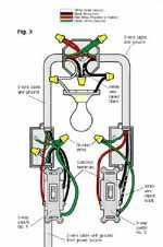
Installing A 3 Way Switch With Wiring Diagrams The Home Improvement.

Seat Belt Circuit Light Circuit Diagram Seat Belt Warning Light.

Wiring Diagram.

Way Switch Wiring Diagram Power Enters At One 3 Way Switch Box.
Way Switch Feed To Switch.

How To Wire A 3 Way Light Switch Wikihow Wikihow.

Wiring A Light Switch End Of.

The Switch Manual Control Of Reversing Light 20a Min Standard Relay.
Tuesday, April 2, 2013
Solve buzzing and noise on the amplifier circuit
Power amplifiers that we sometimes raises a raft of small drone as groundingless than perfect.The following are some ways to cope with the hum of the power amplifier:
1. Keep sensitive circuits of the transformer, casing dimensions are not too small.One blog even suggested to use two-bok, bok special one for the transformer. For the toroid transformer or amplifier with a large transformer, should only contain a series of power amps, with no tone control.
2. Change the position of the transformer, side by side into the lower side (the transformer is high) withfacing a series of sensitive posts
3. Use a spacer on each PCB board as high as half the height of the transformer, eg as high as 2.5 cm or more so that the PCB board parallel to the core / center of the transformer, here the effect of the weakest fields.
4. We recommend using a stereo module instead of two mono modulesThis avoids wiring errors. If forced to, try to sizecable between the right and left modules as long and as short as possible.
5. Should take the ground path for the speaker of ct ct elco instead of the transformer,if the board pcb mounted two big elco (like elco power supply), takeground path of the speakers here, and check to hear!
6. Power supply for radio (TX or RX) is very sensitive, use a capacitor4x100nf, 4 pairs of these capacitors in parallel to each mem-diode (bridge).
7. At the tone control circuit IC op-amp that uses a symmetric power supply,sufficient ground wiring is taken from the signal ground wires only. shouldIC power supply (7812) installed near the main power supply, notmounted near the tone control.
8. Always use a stereo cable shrouded perfect (color stereo cablered-white-covered ground and wrapped in transparent skin.
9. For power supply, use capacitors of 2200uF per ampere elco
10. Zoom and ground wires as short as possible, especially a pair of elco (ct line between elco) power supply (can be tried for the amplifier blazer)
11. For the amplifier should be mounted to the computer casing when not in the ground soil is diground PC casing soil
12. Pairs of each kit to the circuit without passing groundnya nut / baud / spacer. Do not let the existing ground line at the hole pcb connected to the casing / box. Do not follow this ground. ground attached to the casing should have one. if necessary use a plastic spacerovercome the noise:
1. Use the active component (IC) that qualified as TL084, TL074, notLM324. LM324 any brand of noise. TL084 is more guaranteed authentic yellow (ST), not white. For now, the IC TL084 is printed white-work unstable frequencyhigh (treble breaks and more noise). For IC 4558 (NE5532) use plain white silk screening JRC4558D or TL072 - TL082 yellow, LF353 noise. LM741 (NE5534) can be replaced with the Hitachi HA17741, LF351 noise may also, has never been tried.we do not have to look for the brand and the price is more expensive because it is the most low noise.
2. If necessary, the circuit power amplifier OCL, lowering its gain by lowering the value ofresistor in the path gain from 33k to 22k speaker, mimics the gain-clone lower amplifier noise.
3. Should simplify the circuit, the circuit is too complex is more susceptible to noise and interference.
4. Should then potentio / volume mounted on the input-power amplifier, such as professional amplifier without tone control.
Saturday, March 30, 2013
Axletrailer Axles Running Gear Componentstrailer Plug Wiring

Standard Seven Way Plug Wiring Diagram Page 2 Ford Truck.

Heavy Metal Photos Trailer Light Diagram.

Wiring Diagram For Bumper Pull Dump Trailers And Roll Off Dump.

Trailer Pulling Information.

Axle Trailer Axles And Running Gear Components Trailer Plug Wiring.

Generic Diagram Of Trailer Wiring.

Trailer Wiring Connector Diagrams For 6 7 Conductor Plugs.

Wiring Diagram For Trailers Caravans.

Trailer Circuit Wiring.

Pin S Type Caravan Wiring Uk Trailer Parts.
Subscribe to:
Posts (Atom)