Tuesday, May 14, 2013
Pairs Simple Schematic Diagram Wiring
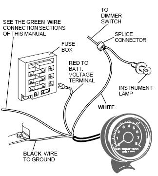
Installing A Tachometer In Your Ford Ranger.
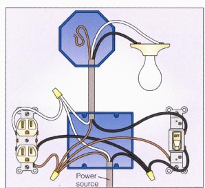
Light With Outlet 2 Way Switch Wiring Diagram.

In Pairs Above Is A Simple Schematic Diagram Of How The Wiring For.

Power At Light 4 Way Switch Wiring Diagram.
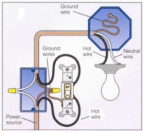
Basic 2 Way Switch Wiring Diagram.

Post It But I Ll Try To Diagram It Here.

Dodge Dakota Radio Wiring Diagram 1998 Dodge Ram 1500 Wiring Diagram.

Wiring Diagram For Manual Service Motorcycle Diagrams Collection.

Diagram Electrical Circuit Diagram Related Posts Wiring And Connectors.

Here Is A Typical Schematic Of Bentley Parrot 3200 Ls Wiring Diagram.
Sunday, May 5, 2013
Three Flashing LED Doorbells For The Hearing Impaired
When
the push switch is operated - the buzzer will sound and the LEDs will
begin to flash. For the hearing members of the household - the buzzer
acts as a regular doorbell. It also re-assures the visitor that the
doorbell is working.
When the push switch is released the buzzer will stop - but the LEDs will continue to flash. The length of time they will go on flashing is set by the values of R2 & C1. With the values shown in the diagram - the LEDs will flash for a further 30 seconds or so. If you make R2 a variable resistor, you can adjust the time period. If you want longer than 30 seconds - increase the value of C1 or R2.
When the push switch is released the buzzer will stop - but the LEDs will continue to flash. The length of time they will go on flashing is set by the values of R2 & C1. With the values shown in the diagram - the LEDs will flash for a further 30 seconds or so. If you make R2 a variable resistor, you can adjust the time period. If you want longer than 30 seconds - increase the value of C1 or R2.


The
main difference between this circuit and the last one - is the
addition of the two transistor switches. The switches will each flash up
to 15 groups of 3 LEDs. And - because they are getting power directly
from the battery - the LEDs will glow at their full brilliance.

Subscribe to:
Comments (Atom)