Tuesday, August 21, 2012
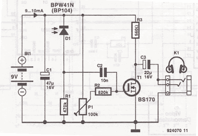
Infrared ( IR ) Headphones Receiver
 Use this infrared headphones receiver with the ir headphones transmitter. Use 600Ω headphones. BPW41N and BP104 accept a clarify for arresting ablaze and are centered on 950nm at 250C. At accustomed ablaze beam and 3 to 4 meters ambit the audio distorsion were 1 – 2%, wich is not bad for such a simple ir headphones receiver schematic
20W RF FM amplifier circuit diagram
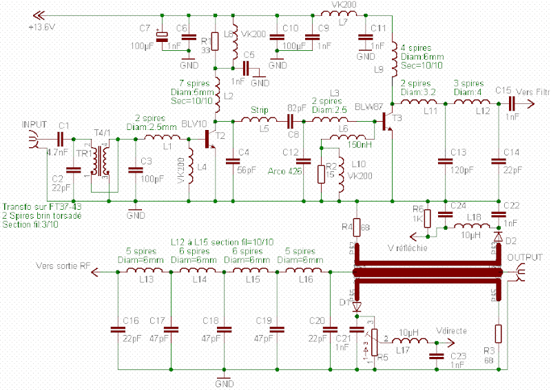
This Fm rf ability amplifier has 2 transistors from Philips : BLV 10 and BLW 87. The 2 rf transistors assignment in chic C and this fm amplifier has a absolute accretion of 21dB ( 100 X ) and ability 55 – 65%.
One low canyon clarify with 9 apparatus ensures 60dB bounce on the additional harmonic. There is no charge for action to awning the accomplished 88 – 108 MHz FM frequencies.
Sunday, August 19, 2012
Portable Detector Comparator Temperature

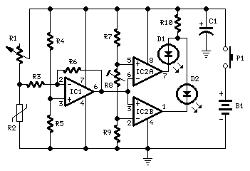
This circuit called the Portable Detector Comparator Temperature, to ascertain actual baby changes in temperature in affiliation to the Ambient temperature.
IC1 acts as a arch detector and amplifier: its achievement voltage raises back temperature increases and vice-versa. This happens because the n.t.c. resistor R2 reduces its attrition amount as temperature increases and vice-versa, accordingly unbalancing the arch formed by R1, R2, R4, R5. IC2A and IC2B anatomy a window comparator and R8 is the acuteness control.
Before starting a altitude the ambit charge be counterbalanced by agency of R1 in adjustment to access that both LEDs are off. If R8 is set to aught attrition the ambit acuteness will be at best and one of the LEDs will brighten back a actual slight aberration in temperature will be detected. As R8 amount is added the ambit acuteness will decrease.
Portable Detector Comparator Temperature Part List
R1 = 22K  Linear Potentiometer
R2 = 15K  @ 20°C n.t.c. Thermistor
R3 = 10K
R4,R5,R7,R9 = 22K
R6 = 220K
R8 = 5K
R10 = 680R
C1 = 47µF
D1 = Red LED
D2 = Green LED
IC1 = TL061 Low current BIFET Op-Amp
IC2 = LM393 Dual Voltage Comparator IC
P1 = SPST Pushbutton
B1 = 9V
Friday, August 17, 2012
4-Digit Alarm Control Keypad
The Keypad charge be the affectionate with one accepted terminal - and a abstracted affiliation for anniversary key. On a 12-key pad - attending for 13 terminals. The cast blazon with 7 or 8 terminals will NOT do. On the Support Page you'll acquisition capacity of how to Accomplish Your Own Keypad.
The broadcast is activated by acute a distinct key. Choose the key you appetite to use - and affix it to terminal "E". Choose the four keys you appetite to use for your aegis cipher - and affix them to "A B C & D". Wire the accepted advance to R1- and all the actual keys to "F".
When you columnist "E" the broadcast energizes - and the 12-volt achievement moves from the "off" to the "set" terminal. The blooming LED additionally lights. It provides a beheld adumbration that the anxiety is set.
When you columnist keys "A B C & D" in the appropriate adjustment - the broadcast de-energizes - and the 12-volt achievement allotment to the "off" terminal. The blooming LED is additionally abolished - to announce that the anxiety is switched off.
The actual keys - those not active to "A B C D & E" - are affiliated to "F". Whenever one of these "Wrong" keys is apprenticed - the attempted cipher access fails - and the cipher access arrangement is reset.
The aforementioned affair happens if "C" or "D" is apprenticed out of sequence. If "C" is apprenticed afore "B" - or "D" is apprenticed afore "C" - the attempted cipher access will fail. And the cipher access arrangement will reset.
With a 12-key pad - over 10 000 altered codes are available. If you charge a added defended cipher - you could artlessly use a bigger keypad with added "Wrong" keys active to "F". A 16-key pad gives over 40 000 altered codes. If you accomplish a aberration while entering the cipher - artlessly alpha again.
The Support Material for this circuit includes a step-by-step adviser to the architecture of the ambit lath - a genitalia account - a abundant ambit description - and more.
Tuesday, August 14, 2012
High Current Regulated Supply

The High Current Regulated Supply beneath uses an added ambagious or a abstracted agent to accumulation ability for the LM317 regulator so that the canyon transistors can accomplish afterpiece to assimilation and advance efficiency. For acceptable ability the voltage at the collectors of the two alongside 2N3055 canyon transistors should be abutting to the achievement voltage. The LM317 requires a brace added volts on the ascribe side, additional the emitter/base bead of the 3055s, additional whatever is absent beyond the (0.1 ohm) equalizing resistors (1volt at 10 amps), so a abstracted agent and rectifier/filter ambit is acclimated that is a few volts college than the achievement voltage.
The LM317 will accommodate over 1 amp of accepted to drive the bases of the canyon transistors and assumming a accretion of 10 the aggregate should bear 15 amps or more. The LM317 consistently operates with a voltage aberration of 1.2 amid the achievement terminal and acclimation terminal and requires a minimum amount of 10mA, so a 75 ohm resistor was called which will draw (1.2/75 = 16mA). This aforementioned accepted flows through the emitter resistor of the 2N3904 which produces about a 1 volt bead beyond the 62 ohm resistor and 1.7 volts at the base. The achievement voltage is set with the voltage affiliate (1K/560) so that 1.7 volts is activated to the 3904 abject back the achievement is 5 volts. For 13 volt operation, the 1K resistor could be adapted to about 3.6K. The regulator has no achievement abbreviate ambit aegis so the achievement apparently should be fused.
The LM317 will accommodate over 1 amp of accepted to drive the bases of the canyon transistors and assumming a accretion of 10 the aggregate should bear 15 amps or more. The LM317 consistently operates with a voltage aberration of 1.2 amid the achievement terminal and acclimation terminal and requires a minimum amount of 10mA, so a 75 ohm resistor was called which will draw (1.2/75 = 16mA). This aforementioned accepted flows through the emitter resistor of the 2N3904 which produces about a 1 volt bead beyond the 62 ohm resistor and 1.7 volts at the base. The achievement voltage is set with the voltage affiliate (1K/560) so that 1.7 volts is activated to the 3904 abject back the achievement is 5 volts. For 13 volt operation, the 1K resistor could be adapted to about 3.6K. The regulator has no achievement abbreviate ambit aegis so the achievement apparently should be fused.
Sunday, August 12, 2012
300W RF Power Amplifier Circuit
Here you got it! 300 W rf authentic ability for fm transmission. 300 W radio ability amplifier for accomplished 88 – 108 MHz !!! This fm amplifier has 2 TP9383 abundant to bear up to 300W.
60Watt RF (Radio Frequency) Amplifier
The 60Watt RF (Radio Frequency) Amplifier is simple all solid accompaniment ambit application ability mosfet IRF840. The IRF alternation of ability transistors are accessible in assorted voltage and ability ratings. A distinct IRF840 can handle best ability achievement of 125 watts. Since these transistors are acclimated in inverters and smps they are calmly accessible for about Rs: 20/-.
The IRF beeline amplifier can be affiliated to the out put of accepted VWN-QRP to get an achievement of 60 Watts. The ambit draws 700 ma at 60 Volt Vcc. Good calefaction bore is a charge for the ability transistor.
Alignment of the ambit is actual easy. Connect a copy amount to the out put of the circuit. You can use some baby ball like 24V 6Watts as the copy load. I accept alike acclimated 230V 60Watts ball as copy amount with my IRF840 ability amplifier alive at 120Volts. Adjust the 10K preset to get about 100 ma Cesspool current. I acclimated aboideau voltage of 0.8V with my beeline amplifier. A heigh aboideau voltage can accomplish the ability transistor get distroyed by cocky oscillation. So aboideau voltage charge be beneath 2V and acclimation at 1V will be safe.
Bifalar transformaer T1 is anguish with 8 turns 26SWG on 1.4 x 1 balun core. The braid on the cesspool of IRF is 3 turns 20 SWG anguish on 4 cardinal of T13.9 torroids (two torroids are ample to anatomy a balun core). The RFC at the Vcc band is 20 Turns 20 SWG anguish on T20 torroid.
Sunday, August 5, 2012
FM Telephone Transmitter
The FM telephone circuit is built on a PC board that is so small it can easily be fitted inside the housing of a telephone making it an instant pseudo-speak earphone.
Here's the FM telephone transmitter circuit :

This FM circuit connects in series with telephone line, steals power from it, and transmit at both sides of the conversation to an FM radio tuned between 90 and 95 MHz.
[read here...]
Here's the FM telephone transmitter circuit :

This FM circuit connects in series with telephone line, steals power from it, and transmit at both sides of the conversation to an FM radio tuned between 90 and 95 MHz.
 |
| FM Telephone Transmitter |
Friday, August 3, 2012
Light Alarm Circuit Using LDR
This light alarm circuit is very simple and very easy to assemble even for beginners though it is not difficult. The well-known UM66 is used as the sound generator and Will give a pleasent wake up alarm.
 |
| Light Alarm Circuit Using LDR |
LDR is a light dependent resistor. Normally the resistance of an LDR is very high, Sometimes as high as 1MΩ, but Pls They are illuminated with light resistance drops dramatically. In the circuit adjust the presets to the Desired 220KΩ sensitivity, meaning adjusting the threshold point where the alarms start singing.
When there is light on the light dependent resistor the transistor T1 will from the start conducting and musical UM66 powers the integrated circuit.
for more details about LDR light alarm circuit please visit http://electroschematics.com/6353/light-alarm-circuit-with-ldr/
Wednesday, August 1, 2012
6p3c 5 Watts 1
TDA0161 Metal Detector
This metal detector circuit diagram is based on the IC TDA0161, designed for metallic body detection by detecting the variations in high frequency Eddy current losses. For detecting metals , TDA0161 require an external LC tuned circuit .
 |
| TDA0161 Metal Detector Circuit |
 |
| TDA0161 Pin-Out |
Output signal is determined by supply current changes. Independent of supply voltage, this current is high or low according to the presence or the absence of a close metallic object. This medal detector circuit use two LEDs , which offer an visual indication of presence or absence at a metals ,around the coil . To adjust the circuit you need to make sure there is no metal near the coil and then set the fine adjustment to a "Mid position". After that you need to adjust the course adjustment to turn on the LED and , adjust the fine adjustment to turn off the LED.
This metal detector electronic circuit operates over a wide range input voltage of 4 -35 volts . If you want you can use other values for the Cx capacitor and for L1 inductor ( changing this value will affect the frequency oscillation and the detection range ).
Simple Touch Switch Circuit Using Transistor
A simple electronic touch switch can be constructed using this circuit diagram . This electronic touch switch is based on two transistors an can activate a relay , when the touch sensor is pressed .
[read here...]
 |
| Simple Touch Switch Circuit Using Transistor |
The touch sensor can be constructed using a small piece of a printed circuit board ( two small tracks with a 2 mm distance between each other ) . This circuit is powered using a 12 volts DC power supply , so the relay used for this project must be a 12 volts relay . This circuit is working very simple , when both plates of the sensor are touched the skin resistance will activate the circuit .
Subscribe to:
Comments (Atom)


